Ford Mustang (1999-2004) Service Manual: Disassembly
1. Inspect the clutch cylinder thrust surfaces, piston bore and clutch plate serrations for scores or burrs. Minor scores or burrs may be removed with a crocus cloth. Install a new clutch cylinder if badly scored or damaged.
2. Check fluid passage in the clutch cylinder for obstructions. Clean out all fluid passages. Inspect the clutch piston for scores and install new if necessary. Inspect check balls for freedom of movement and correct seating.
3. Check clutch release spring for distortion and cracks. Install a new spring (including the wave spring) if distorted or cracked.
4. Inspect the composition clutch plates, steel clutch plates and clutch pressure plate for worn or scored bearing surfaces. Install new parts if they are deeply scored or burred.
5. Check the clutch plates for flatness and fit on clutch hub serrations. Discard any plate that does not slide freely on serrations or that is not flat.
6. Check clutch hub thrust surfaces for scores and clutch hub splines for wear.
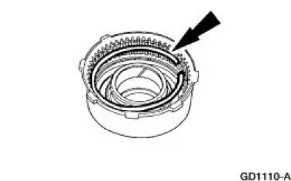
7. Remove the No. 2 forward clutch bearing.
8. Remove the reverse clutch selective retaining ring.
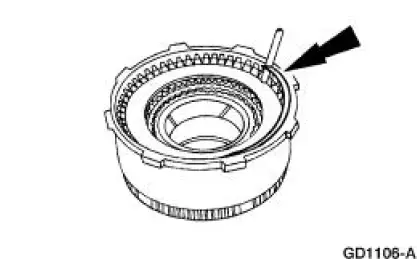
9. Remove the reverse clutch pack.
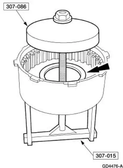
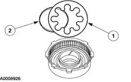
10. Using the special tools, compress the reverse clutch piston spring.
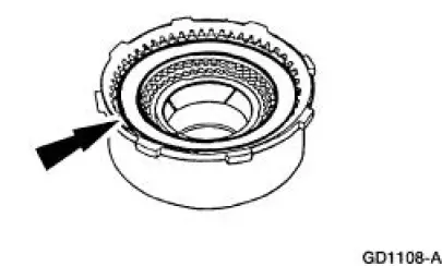
11. Remove the reverse clutch piston spring retaining ring.
12. Remove the reverse clutch piston spring pressure ring.
1. Remove the reverse clutch piston spring.
2. Remove the reverse clutch piston spring pressure ring.
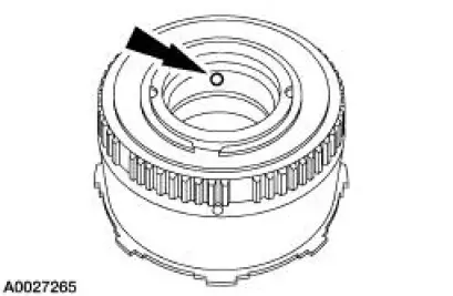
13. NOTE: To ease reverse clutch piston removal, it may be necessary to apply air pressure to the reverse clutch drum. Block the opposite hole.
Remove the reverse clutch piston.
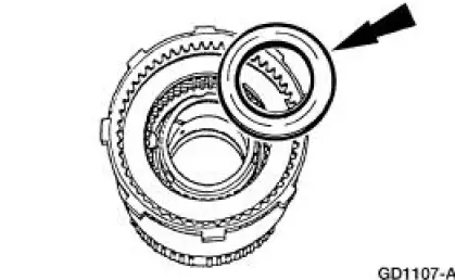
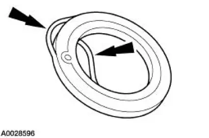
14. Remove the reverse clutch piston inner and outer seals.
 Reverse Clutch
Special Tool(s)
Dial Indicator Gauge with
Holding Fixture
100-002 (TOOL-4201-C)
Compressor, Clutch Spring
307-015 (T65L-77515-A)
Protector, Transmission
Reve ...
 Assembly
1. NOTE: One tab that locks the reverse clutch drum into the reverse
sun shell may be removed.
This is done for balancing purposes.
Inspect the clutch cylinder thrust surfaces, piston bore and clut ...
Other materials:
Rear Spoiler
Removal and Installation
1. Open the luggage compartment lid.
2. Disconnect the high mounted stoplamp electrical connector.
3. Remove the screws and the nuts.
4. CAUTION: Use care not damge the pin-type retainers and pin-type
retainer seals
during re ...
Actuator Cable - Speed Control
1. Remove the speed control actuator cable end from the throttle body.
1. Lift the speed control cable from the throttle nailhead.
2. Release the speed control cable from the throttle bracket.
2. Remove the speed control cable from the retaining cli ...
A/C Compressor Pressure Relief Valve
An A/C compressor pressure relief valve is incorporated into the compressor
A/C manifold and tube to:
relieve unusually high refrigerant system discharge pressure buildups.
For specifications
regarding operating pressure(s), refer to Section.
prevent ...
