Ford Mustang (1999-2004) Service Manual: Dual Converter H-Pipe - 4.6L (2V and 4V)
Removal
NOTE: The RH and LH catalytic converters are serviced separately.
1. Raise and support the vehicle. For additional information, refer to Section.
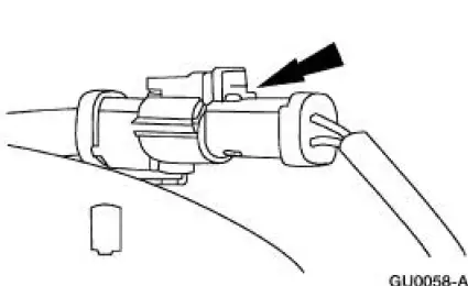
2. CAUTION: When repairing exhaust system or removing the exhaust components, disconnect all heated oxygen sensors (HO2S) (9F472) at the wiring connectors to prevent damage to the heated oxygen sensors and wiring harness.
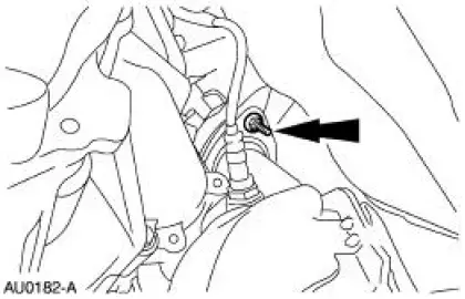
Disconnect the downstream RH and LH heated oxygen sensor connectors (9F472).
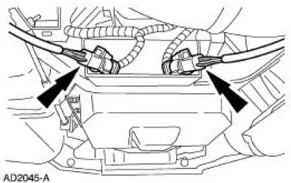
3. Disconnect the two upstream RH and LH catalyst monitor sensor connectors.
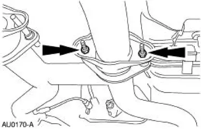
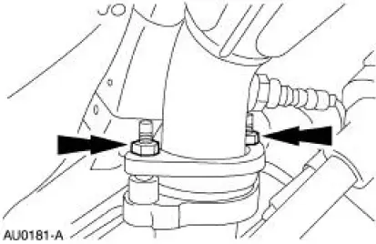
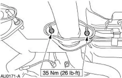
4. Remove the dual converter assembly nuts. (RH shown, LH similar.)
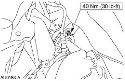
5. Remove the RH exhaust manifold flange nuts.
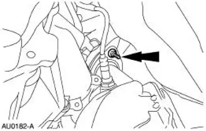
6. Remove the LH exhaust manifold flange nuts.
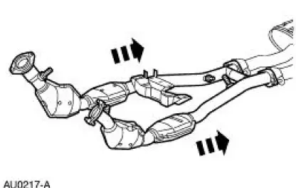
7. Remove the dual converter H-pipe.
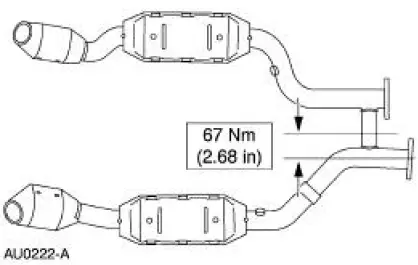
8. If necessary, use the center of the LH flange as a baseline, measure 67 mm (2.68 in) and cut the cross-over pipe.
9. If necessary, use the center of the RH flange as a baseline, measure 83.9 mm (3.35 in) and cut the cross-over pipe.
Installation
1. Position the LH and RH dual converter pipe.
- Snug the converter-to-manifold nuts.
2. Position the muffler and install the dual converter assembly nuts. (RH shown, LH similar.)
3. If necessary, position the sleeve and clamps. Tighten the clamps to 55 Nm (41 lb-ft).
4. Tighten the four converter-to-manifold nuts.
5. Connect the two upstream RH and LH heated oxygen sensor connectors.
6. Connect the two downstream RH and LH catalyst monitor sensor connectors.
 Dual Converter Y-Pipe - 3.8L
Removal
NOTE: The RH and LH catalytic converters are serviceable separately.
1. Raise and support the vehicle. For additional information, refer to
Section.
2. CAUTION: When repairing the exhaust sys ...
 Fuel System
...
Other materials:
Instrument Cluster (Diagnosis and Testing)
Refer to Wiring Diagrams Cell 60 , Instrument Cluster for schematic and
connector information.
Special Tool(s)
Worldwide Diagnostic System
(WDS)
418-F224,
New Generation STAR (NGS)
Tester
418-F052, or equivalent
diagnostic tool
...
Assembly
1. CAUTION: 118 ml (4 oz) of the specified Ford Friction Modifier must
be used in the
axle.
Lubricate each steel clutch plate and soak all friction plates for no less than
15 minutes.
Use Additive Friction Modifier C8AZ-19B546-A or equivalent meeting Ford ...
Installation
1. Install the lower intake manifold gaskets.
2. Connect the fuel charging wiring harness to the rear of the lower intake
manifold and install the
manifold.
3. Install the intake manifold fasteners and tighten in the sequence shown.
4. Position the fuel ...
