Ford Mustang (1999-2004) Service Manual: Installation
1. Install the spring.
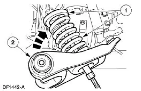
1. Position the spring and spring insulator in the front suspension lower control arm.
2. Swing the arm into the fender well.
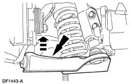
2. Position a jack stand under the front suspension lower control arm inboard of the spring seat and raise the arm into position.
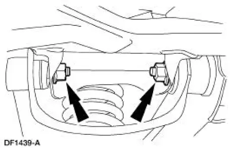
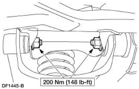
3. NOTE: The front suspension lower arm nuts must be tightened with the suspension at curb height.
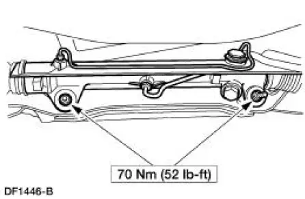
Install the bolts and nuts. Do not tighten the bolts at this time.
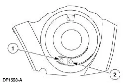
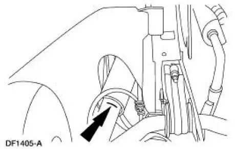
4. Make sure the spring is correctly positioned in the front suspension lower arm.
1. Spring must not cover this hole.
2. Spring must cover this hole.
5. Remove the special tool.
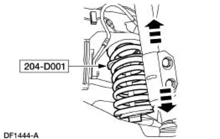
6. Move the jack stand under the front suspension lower arm ball joint and raise the suspension until the shock absorber is compressed to the previously established alignment mark (curb height).
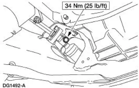
7. Tighten the nuts.
8. Remove the jack stand.
9. Install the power rack and pinion steering gear.
10. Position the intermediate shaft and install the bolt.
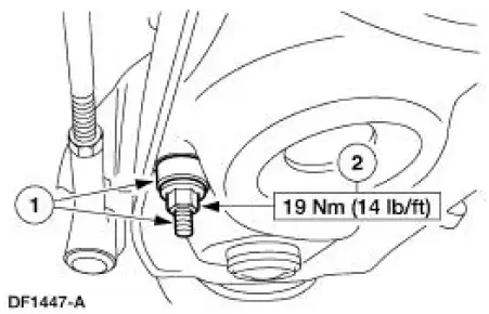
11. Connect the stabilizer bar link to the front suspension lower arm.
1. Install the link and bushing.
2. Install the nut.
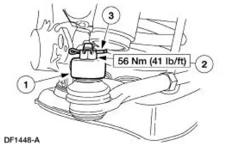
12. Connect the tie-rod end to the spindle.
1. Install the tie-rod end into the spindle.
2. Install the nut.
3. Install a new cotter pin.
13. Install the wheel and tire assembly. 14. Lower the vehicle.
15. Check wheel alignment. Adjust if necessary.
 Removal
CAUTION: Suspension fasteners are critical parts because they affect
performance of vital
components and systems and their failure can result in major service expense. A
new part with
the same part ...
 Rear Suspension
Torque Specifications
WARNING: All vehicles are equipped with gas pressurized shock absorbers
which will
extend unassisted. Do not apply heat or flame to the shock absorbers during
removal or
comp ...
Other materials:
Reservoir - CIII Pump
Removal
1. Remove the bolts.
2. Disconnect the power steering hoses. Remove the reservoir.
Installation
1. To install, reverse the removal procedure.
2. Fill and leak check the power steering system. ...
Driving through water
WARNING: Drive through water in an emergency only, and not
as part of normal driving.
WARNING: Engine damage can occur if water enters the air
filter.
Note: Driving through deep water may allow water into the transmission
or air intake and can cause internal v ...
Front Seat Backrest
Removal and Installation
All vehicles
1. Remove the seat. For additional information, refer to Seat-Front Power
in this section.
2. Remove the front seat backrest latch. For additional information, refer
to Latch-Front Seat
Backrest in this section.
...
