Ford Mustang (1999-2004) Service Manual: Installation
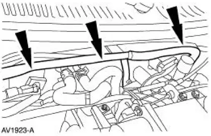
1. Position the fuel charging wiring in the vehicle and attach to the rear of the intake manifold.
2. NOTE: Make sure the locking clips are fully engaged into the bracket.
Reposition the accelerator cable and the speed control cable (if equipped) and install the cables into the bracket.
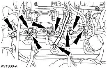
3. Connect the vacuum lines.
4. Connect the main vacuum hose.
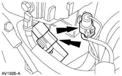
5. Connect the two connectors.
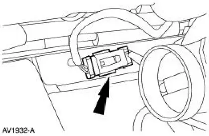
6. Install the battery supply wire, tighten the nut and close the cover.
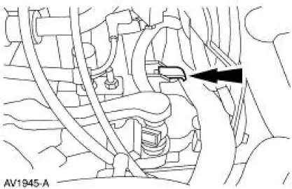
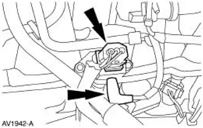
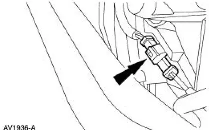
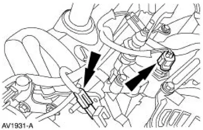
7. Connect the fuel pressure sensor and the vacuum hose.
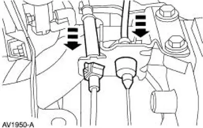
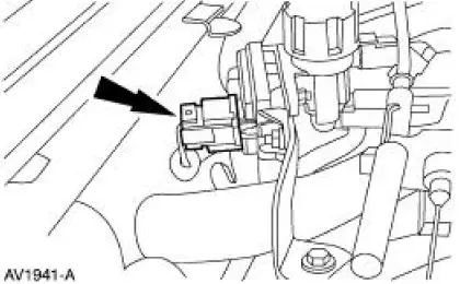
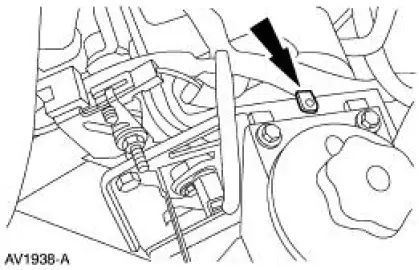
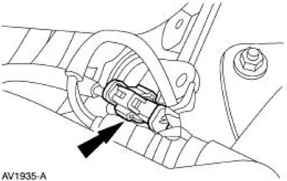
8. Connect the EGR pressure transducer electrical connector.
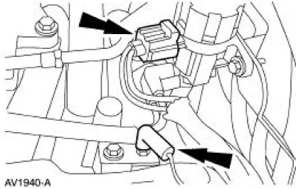
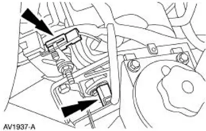
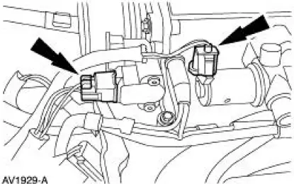
9. Connect the following connectors:
- Ground wire
- Exhaust vacuum regulator (EVR)
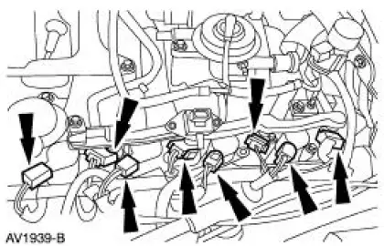
10. Connect the following connectors:
- LH fuel injectors
- LH ignition coils
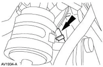
11. Connect the following generator connectors:
- Voltage regulator
- Battery supply
12. Install the wiring harness retainers to the power steering reservoir bracket.
13. Connect the following connectors:
- LH radio ignition interference capacitor
- CMP sensor
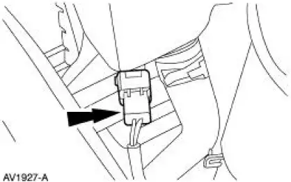
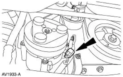
14. Connect the coolant reservoir electrical connector.
15. Raise the vehicle.
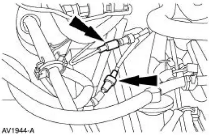
16. Connect the LH (HO2S) electrical connector.
17. Connect the RH (HO2S) electrical connector.
18. Connect the A/C compressor clutch electrical connector.
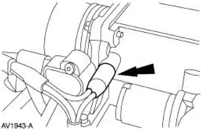
19. Connect the CKP electrical connector.
20. Lower the vehicle.
21. Connect the 16 pin connector.
22. Connect the following connectors:
- ECT sensor
- RH radio ignition interference capacitor
23. Connect the following connectors:
- PCV hose
- Four fuel injectors
- Four ignition coils
24. Connect the following connectors:
- IAC valve
- TP sensor
25. Install the wiring harness retainers to the dash panel.
26. Connect the 42 pin connector.
27. Connect the air cleaner outlet tube.
28. Connect the battery ground cable.
 Removal
WARNING: Do not smoke or carry lighted tobacco or open flame of any
type when
working on or near any fuel related components. Highly flammable mixtures are
always present
and may be ignited. Failure ...

Other materials:
Exhaust Manifold to Exhaust Gas Recirculation (EGR)
Valve Tube - Cobra
Removal and Installation
1. Remove the EGR valve. For addditional information, refer to Exhaust
Gas Recirculation (EGR)
Valve-Cobra in this section.
2. With the vehicle in NEUTRAL, position it on a hoist.
3. Disconnect the exhaust manifold to EGR valve ...
Electronic compass
The compass heading displays in the center-integrated display.
Note: Driving near large buildings, bridges, power lines and powerful
broadcast antenna may affect the compass reading. Magnetic or metallic
objects placed in, on or near your vehicle may also aff ...
Caliper (Removal and Installation)
Special Tool(s)
Rear Caliper Piston Adjuster
206-026 (T87P-2588-A)
Removal
1. Raise the vehicle on a hoist.
2. Remove the wheel and tire assembly.
3. Disengage the parking brake cable end from the parking brake lever
arm.
4. Remov ...
