Ford Mustang (2005-2014) Owners Manual: Head restraints
WARNING: To minimize the risk of neck injury in the event of a crash, the driver and passenger occupants should not sit in or operate the vehicle, until the head restraint is placed in its proper position. The driver should never adjust the head restraint while the vehicle is in motion.
WARNING: The adjustable head restraint is a safety device.
Whenever possible it should be installed and properly adjusted when the seat is occupied.
WARNING: Install the head restraint properly to minimize the risk of neck injury in the event of a crash.
Note: Before adjusting any head restraint, adjust the seat back to an upright driving or riding position. Properly adjust the head restraint so that the top of the head restraint is even with the top of your head and positioned as close as possible to the back of your head. For occupants of extremely tall stature, adjust the head restraint to its full up position.
To adjust the head restraint, do the following:
Front Seat Head Restraints (If Equipped)
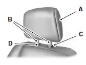
The head restraints consist of:
A. An energy absorbing head
restraint
B. Two steel stems
C. Guide sleeve adjust and release
button
D. Guide sleeve unlock and remove
button
• Raise: Pull up on the head restraint (A).
• Lower: Press and hold the guide sleeve adjust and release button (C)
and push down on the head restraint (A).
• Remove: Pull up the head restraint until it reaches the highest
adjustment position and then press and hold both the adjust and
release button (C) and the unlock and remove button (D), then pull
up on the head restraint.
• Reinstall: Align the steel stems into the guide sleeves and push the
head restraint down until it locks.
Front Seat Non-adjustable Head Restraints (If Equipped)
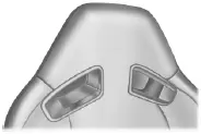
The non-adjustable head restraints consist of a trimmed foam covering over the upper structure of the seat back.
Properly adjust the seat back to an upright driving/riding position, so that the head restraint is positioned as close as possible to the back of your head.
Rear Seat Non-adjustable Outboard Head Restraints
The second row outboard non-adjustable head restraints can be rotated forward to improve rear vision when there are no rear occupants.
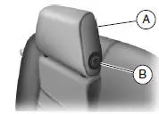
The non-adjustable head restraints consist of:
A. a trimmed energy absorbing foam
and structure
B. a rotation button.
Press the rotation button to rotate the head restraint forward in order to improve rear vision when there are no rear seat occupants.
Properly adjust the head restraint to an upright driving or riding position by lifting up on the head restraint until it locks into its original position.
Tilting Head Restraints (If Equipped)
The front head restraints may have a tilting feature for extra comfort.
To tilt the head restraint, do the following:
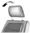
1. Adjust the seat back to an upright driving or
riding position.
2. Tilt the head restraint forward by gently pulling
the top of the head restraint.
Once it is in its forward-most position, tilt it forward once more to release it to the upright position.
Note: Do not attempt to force the head restraint backward after it is tilted. Instead, continue tilting it forward until the head restraint releases to the upright position.
 Sitting in the correct position
WARNING: Sitting improperly out of position or with the seat
back reclined too far can take off weight from the seat cushion
and affect the decision of the passenger sensing system, resulting in
serio ...
 Manual seats
WARNING: Do not adjust the driver’s seat or seatback while the
vehicle is moving.
WARNING: Rock the seat backwards and forwards after
releasing the lever to make sure that it is fully engaged.
Movi ...
Other materials:
Disassembly
1. Remove the driveshaft (4602). For additional information, refer to
Driveshaft in this section.
2. CAUTION: Under no circumstances is the driveshaft assembly to be
clamped in the
jaws of a vise or similar holding fixture. Denting or localizing fracture ca ...
Accelerator Cable Bracket - Supercharged Engine
Removal and Installation
1. Disconnect the accelerator cable and speed control cable.
2. Depress the tabs and disconnect the accelerator cable and speed control
cable from the
accelerator cable bracket
3. Remove the bolts and the accelerator cable bracket ...
Subwoofer Speaker - Convertible
Removal and Installation
1. Remove the rear quarter trim panel. For additional information,
refer to Section .
2. Remove the subwoofer assembly.
1. Disconnect the electrical connectors.
2. Remove the screws.
3. Remove the subwoofer assemb ...
