Ford Mustang (1999-2004) Service Manual: Installation
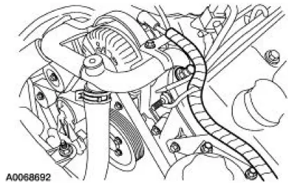
1. Position the wiring harness:
- Install the wiring harness retainer onto the LH valve cover stud bolt.
- Install the wiring harness retainer into the power steering reservoir.
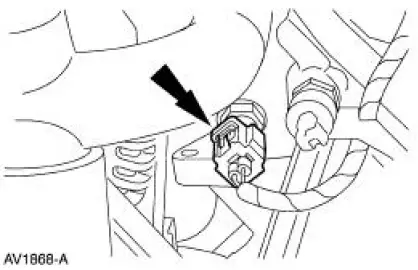
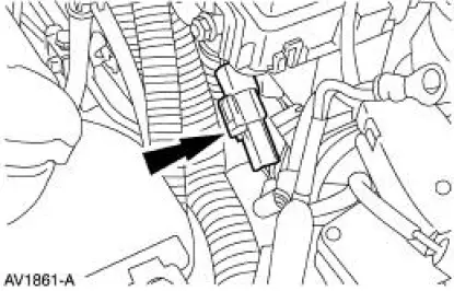
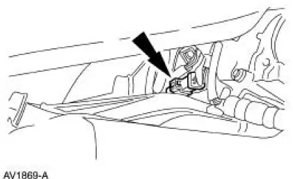
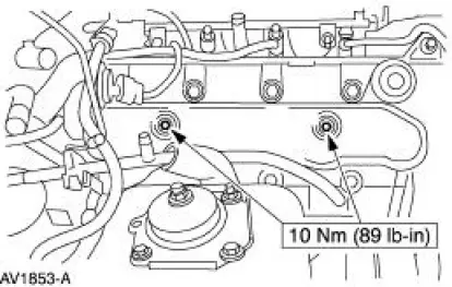
2. Connect the ECT sensor electrical connector.
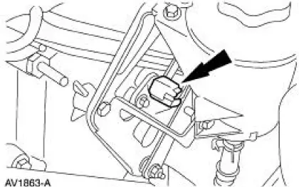
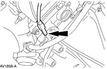
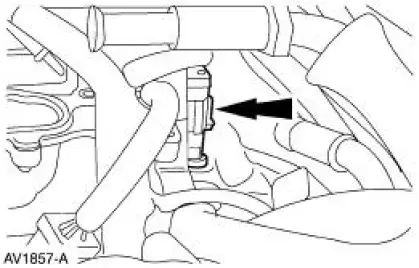
3. Connect the CMP sensor electrical connector.
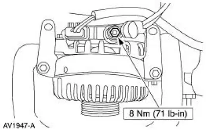
4. Connect the following generator electrical connectors:
- Battery power supply wire.
- Voltage regulator.
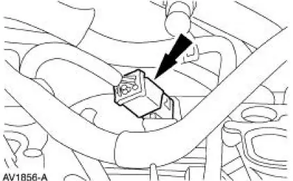
5. Connect the electrical connector.
6. Connect the electrical connector.
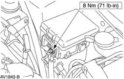
7. Install the battery supply wire to the power distribution box stud.
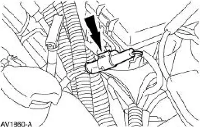
8. NOTE: LH side is shown, RH side is similar.
Connect the two radio ignition interference capacitor electrical connectors.
9. Connect the RH HO2S electrical connector.
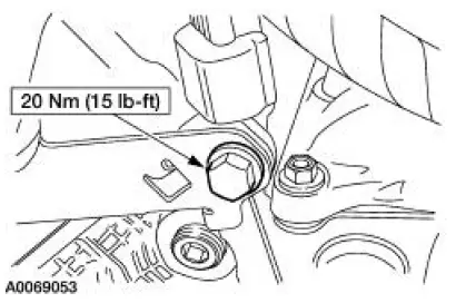
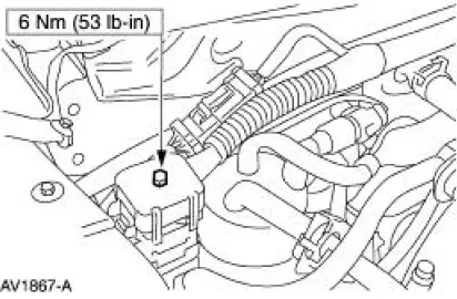
10. Install the wiring harness bracket bolt.
11. Connect the engine control jumper harness electrical connector.
12. Connect the transmission main control harness electrical connector.
13. Connect the LH ignition coil electrical connectors.
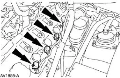
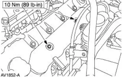
14. Install the LH ignition coil cover and bolts.
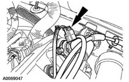
15. Connect the heated positive crankcase ventilation (PCV) vlave electrical connector.
16. Connect the RH ignition coil electrical connectors.
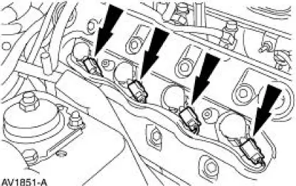
17. Install the RH ignition coil cover and bolts.
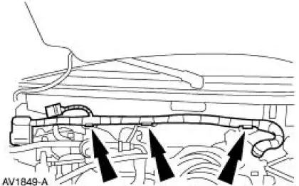
18. Install the wiring harness retainers into the dash panel.
19. Connect the following connectors:
- The 42 pin engine bulkhead electrical connector.
- The 16 pin electrical connector.
20. Install the upper intake manifold. For additional information, refer to Section.
21. NOTE: When the battery is disconnected and reconnected, some abnormal drive symptoms may occur while the vehicle relearns its adaptive strategy. The vehicle may need to be driven 16 km (10 mi) or more to relearn the strategy.
Connect the battery ground cable. For additional information, refer to Section.
 Removal
WARNING: Do not smoke or carry lighted tobacco or open flame of any
type when
working on or near any fuel related components. Highly flammable mixtures are
always present
and can ignite. Failure to ...
 Supply Manifold
Removal
WARNING: Do not smoke or carry lighted tobacco or open flame of any
type when
working on or near any fuel related components. Highly flammable mixtures are
always present
and can ignite. Fai ...
Other materials:
Crankshaft Position (CKP) Sensor - 3.8L
Removal
1. Disconnect the battery ground cable. For additional information,
refer to Section.
2. Remove the crankshaft position (CKP) sensor.
Disconnect the connector.
Remove the bolts and the sensor.
Installation
1. To install, reverse ...
Technical specifications
Wheel Lug Nut Torque Specifications
WARNING: When a wheel is installed, always remove any
corrosion, dirt or foreign materials present on the mounting
surfaces of the wheel or the surface of the wheel hub, brake drum or
brake disc that contacts the wheel. Make ...
Pinpoint Tests
PINPOINT TEST A: THE ENGINE DOES NOT CRANK AND THE
RELAY DOES CLICK
Test Step
Result / Action to Take
A1 CHECK THE VOLTAGE TO THE STARTER RELAY
YesGO to A2 .
No
REPAIR circuit 1050 (LG/VT) for an open. TEST the
system for normal operation. ...
