Ford Mustang (1999-2004) Service Manual: Removal
CAUTION: Suspension fasteners are critical parts because they affect performance of vital components and systems and their failure can result in major service expense. A new part with the same part number must be installed if installation becomes necessary. If substitution is necessary, the part must be of the same finish and property class. Torque values must be used as specified during reassembly to make sure of correct retention of these parts.
1. Remove the rear wheel knuckle (5A968/5A969). For additional information, refer to Wheel Knuckle-Cobra in this section.
2. Remove the bolts and the dust shield. Discard the bolts.
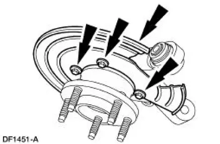
3. Position the knuckle in a vise.
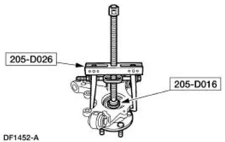
4. NOTE: There are two methods for removing the rear hub (1109) from the rear wheel bearing (1A049). Both methods are shown.
Method one. Using the special tools, remove the hub.
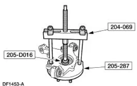
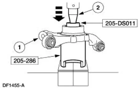
5. Method two. Using the special tools, remove the hub.
6. Remove the snap ring.
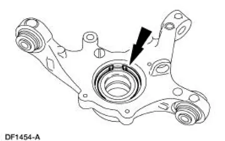
7. Press the wheel bearing from the knuckle.
1. Position the knuckle on the press bed supported by the special tool.
2. Using the appropriate step plate adapter, press the bearing from the knuckle.
 Wheel Hub - Cobra
Special Tool(s)
2-3 Jaw Puller
205-D026 (D80L-1013-A) or
Equivalent
Driver
205-199 (T83T-3132-A1)
Front Hub Remover Replacer
204-069 (T81P-1104-C)
...
 Installation
1. Install the bearing.
1. Position the knuckle on the press.
2. Using the appropriate step plate adapter, press the bearing into the
knuckle until the
bearing clears the snap ring groove and b ...
Other materials:
Crankshaft Runout
Special Tool(s)
Dial Indicator Gauge with
Holding Fixture
100-002 (TOOL-4201-C) or
equivalent
1. NOTE: Crankshaft main bearing journals must be within
specifications before checking runout.
Use the Dial Indicator Gauge with Holding Fixtur ...
Engine (Assembly)
Special Tool(s)
Guides, Connecting Rod
303-442 (T93P-6136-A)
Installer, Crankshaft Vibration
Damper
303-102 (T74P-6316-B)
Installer, Front Cover Oil Seal
303-335 (T88T-6701-A)
Installer, Crankshaft Rear ...
Principles of Operation
The speed control system is designed to maintain vehicle speed above 48 km/h
(30 mph). After the
ON switch is depressed, depressing the SET/ACCEL switch will activate the speed
control servo. To
increase a set speed, either depress and hold for continuous ac ...
