Ford Mustang (1999-2004) Service Manual: Clutch Controls (Description and Operation)
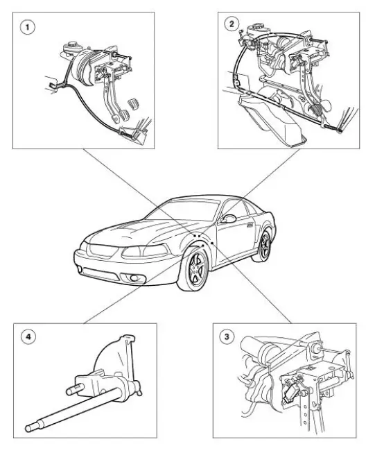
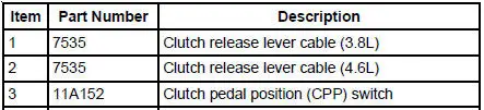

The clutch control system engages and disengages the clutch. The clutch control system disengages the clutch when the clutch pedal is depressed and engages the clutch when the clutch pedal is released. Clutch pedal motion is transmitted by the clutch release lever cable to the clutch release lever. The clutch release hub and bearing engages the clutch pressure plate diaphragm spring, releasing the pressure on the clutch disc which in turn disengages the transmission from the engine.
The clutch adjusts automatically to compensate for clutch disc wear. The clutch linkage is selfadjusting.
The clutch pedal position (CPP) switch prevents the starter motor from engaging unless the clutch pedal is depressed all the way to the floor. The switch plunger is contacted by the clutch pedal and extends as the clutch pedal is pressed. The clutch pedal position switch is electrically connected in line with the ignition switch and the starter motor relay coil. The CPP also turns off the speed control when the clutch pedal is depressed.
 Clutch Controls
General Specifications
Torque Specifications
...
 Clutch Pedal - Quadrant and Pawl Assembly
Removal
1. Disconnect the battery ground cable (14301).
2. Loosen the nut from inside the engine compartment.
3. Loosen the nuts from inside the vehicle.
4. Loosen the screw.
5. Disconnect t ...
Other materials:
Rear Spoiler
Removal and Installation
1. Open the luggage compartment lid.
2. Disconnect the high mounted stoplamp electrical connector.
3. Remove the screws and the nuts.
4. CAUTION: Use care not damge the pin-type retainers and pin-type
retainer seals
during re ...
Transmission Support Crossmember
Removal and Installation
1. Raise and support the vehicle. For additional information, refer to
Section.
2. Support the transmission with a suitable transmission jack.
3. Remove the crossmember.
1. Disconnect the HO2S sensors and position them aside.
2. ...
Exhaust Gas Recirculation (EGR) Valve - Mach I
Removal and Installation
1. Remove the air intake scoop. For additional information, refer to
Section.
2. Remove the exhaust gas recirculation (EGR) valve.
1. Disconnect the EGR tube upper fitting.
2. Disconnect the vacuum hose.
3. Remove the tw ...
