Ford Mustang (1999-2004) Service Manual: Installation
1. Align the center mark on the cover assembly to the V-notch on the rear glass assembly and staple the entire length of the number four bow.
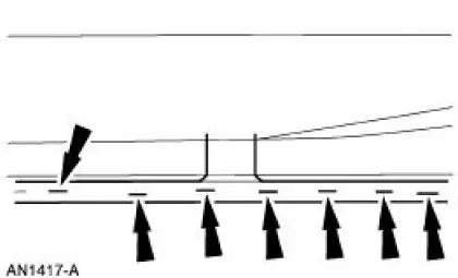
2. Center the listing sleeve on the bottom of the folding top number two bow.
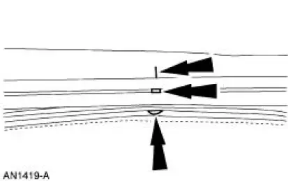
3. Position the listing sleeve onto the number two bow with the headliner retainer.
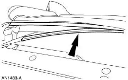
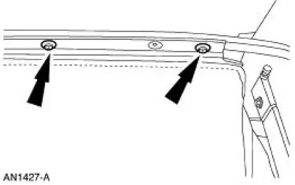
4. Install the screws for the number two bow.
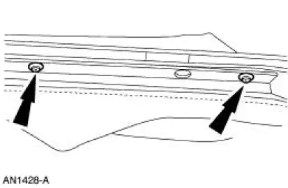
5. Pull the roof headlining over the top of the folding top header (number one bow) and staple the underside.
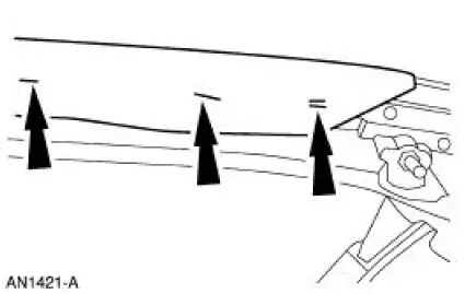
6. Connect the headliner front elastic strip with the speed nut.
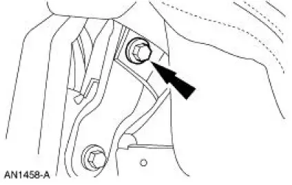
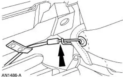
7. Pull the folding top tension cable through the retainer in the roof outside cover.
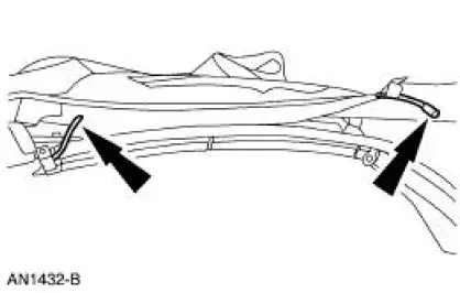
8. Engage the cable to the spring retainer.
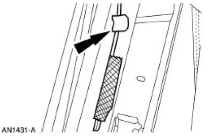
9. Staple the flap at the front of the roof outside cover to the tacking strip on the underside of the folding top header panel.
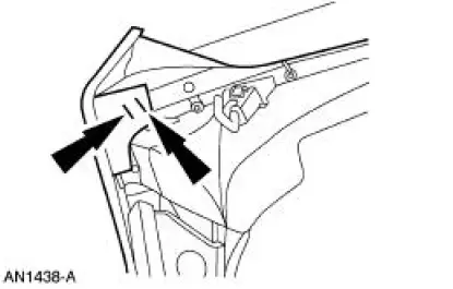
10. Pull the front corner of the roof outside cover over the folding top header and staple to the tacking strip.
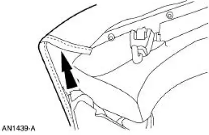
11. Fold the tab under the folding top header (number one bow) and clamp.
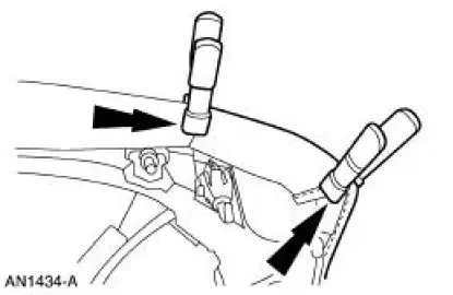
12. Staple the rear of the roof outside cover to the side tacking strip.
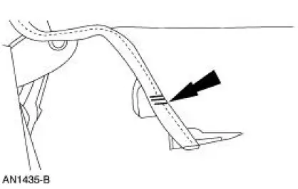
13. NOTE: Make sure there are no wrinkles in the roof outside cover.
Install the remaining staples along the rear of the roof outside cover.
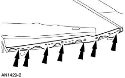
14. Install the folding top tension cable through the eyelet of the roof outside cover.
15. Position the headliner retainer to the number three and four bow and install the screws.
16. NOTE: Make sure there are no wrinkles on the top of the roof outside cover.
Support the top and staple the underside of the folding top header panel from the center to the sides.
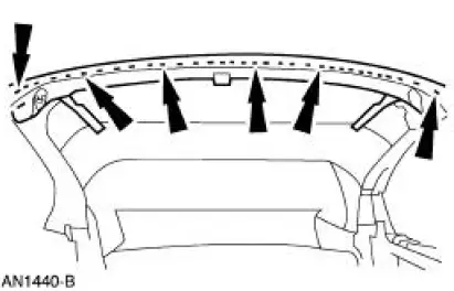
17. Install the screws through the headlining and the strap into the front side rail.
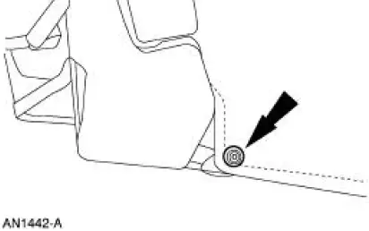
18. Position the center elastic strap to the rear of the folding top center rail and install the screw.
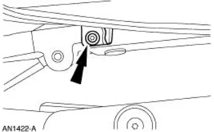
19. Position the rear elastic strap and install the screw.
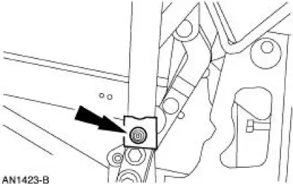
20. Position the rear elastic strap and install the screw.
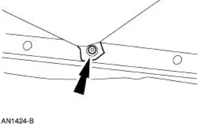
21. Trim the excess roof outside cover along the rear tacking strips and around the tacking strip mounting holes.
22. NOTE: Install new plastic roof headlining retaining pins if they were removed.
Engage the roof headlining into the folding roof rear side rail.
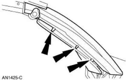
23. Install the seal compression panel.
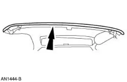
24. Install two-sided tape on the rear rail.
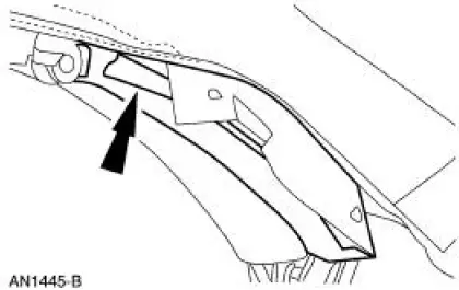
25. Install the flap onto the rear rail.
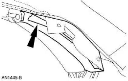
26. Install the rear weatherstrip retainers.
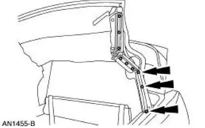
27. Install the clips.
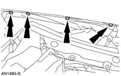
28. Install the exterior mouldings.
 Removal
1. Remove the rear exterior trim mouldings.
2. Remove the clips
3. Remove the 13 Torx screws and the seal compression panel.
4. Remove the staples.
5. Remove the staples from the number one b ...
 Stay Pad - Convertible Top
Removal
1. Remove the convertible top material. For additional information, refer to
Convertible Top
Material in this section.
2. Remove the rear window glass. For additional information, refer to
...
Other materials:
Valve Cover RH
Material
Item
Specification
Silicone Gasket and Sealant
F7AZ-19554-EA or equivalent
WSE-M4G323-A4
Removal and Installation
1. Remove the air cleaner outlet tube. For additional information, refer to
Section.
2. Disconnect the fuel line. F ...
Removal
All vehicles
1. Remove the air intake scoop bracket. For additional information, refer to
Section.
2. Remove the RH valve cover. For additional information, refer to Valve Cover
RH in this section.
3. Remove the Hydro-Boost brake booster. For additional in ...
Child restraint and safety belt maintenance
Inspect the vehicle safety belts and child safety seat systems periodically
to
make sure they work properly and are not damaged. Inspect the vehicle
and child seat safety belts to make sure there are no nicks, tears or cuts.
Replace if necessary. All vehicle ...
