Ford Mustang (1999-2004) Service Manual: Installation
1. NOTE: If the lower intake manifold is not secured within four minutes, the sealant must be removed and the sealing area cleaned with metal surface cleaner. Allow to dry until there is no sign of wetness, or four minutes, whichever is longer. Failure to follow this procedure can cause future oil leakage.
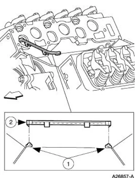
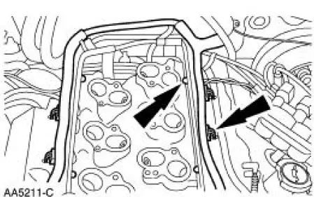
Install the lower intake manifold front and rear end seals.
1. Apply a bead of silicone gasket and sealant to the intake manifold front and rear end seal mounting points as indicated.
2. Install the lower intake manifold front and rear end seals.
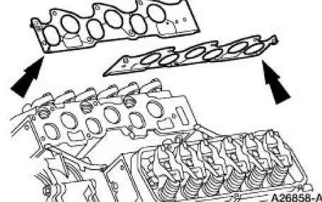
2. Install the intake manifold gaskets.
3. NOTE: If the lower intake manifold is not secured within four minutes, the sealant must be removed and the sealing area cleaned with metal surface cleaner. Allow to dry until there is no sign of wetness, or four minutes, whichever is longer. Failure to follow this procedure can cause future oil leakage.
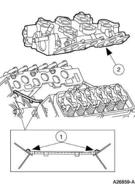
Position the lower intake manifold.
1. Apply a bead of silicone gasket and sealant to the lower intake manifold mounting at the points indicated.
2. Position the lower intake manifold.
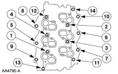
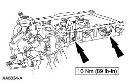
4. NOTE: Refer to the location note made during removal and make sure the bolts are installed in the correct location.
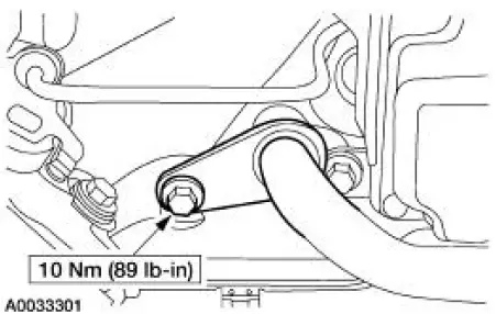
Tighten the bolts in two stages in the sequence shown:
- Stage 1: Tighten the bolts to 5 Nm (44 lb-in).
- Stage 2: Tighten the bolts to 10 Nm (89 lb-in).
5. NOTE: Install the fuel injection supply manifold and fuel injectors as an assembly.
Install the fuel injector supply manifold and bolts.
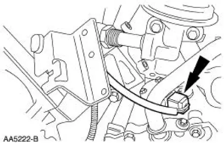
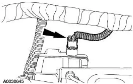
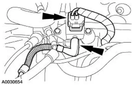
6. Connect the electrical connector.
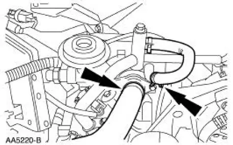
7. Connect the coolant hoses.
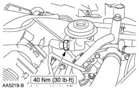
8. Connect the EGR tube.
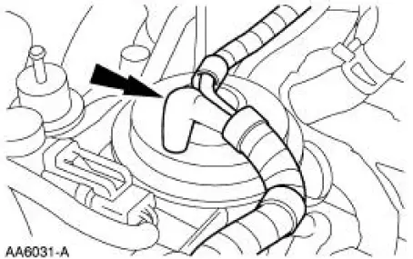
9. Connect the EGR vacuum tube.
10. Lubricate the O-ring with water and install the heater hose.
11. Install the heater bypass tube. For additional information, refer to Section.
12. Connect the IMRC electrical connector.
13. Position and connect the engine wire harness. Install the pin-type retainers.
14. Connect the fuel supply tube spring lock coupling. For additional information, refer to Section.
15. Connect the FRP sensor electrical connector and the vacuum hose.
16. Install the upper intake manifold. For additional information, refer to Upper Intake Manifold in this section.
17. CAUTION: Correct cooling system bleeding is critical for correct engine cooling.
Fill and bleed the cooling system. For additional information, refer to Section.
 Removal
1. Remove the upper intake manifold. For additional information, refer to
Upper Intake Manifold in
this section.
2. Partially drain the cooling system. For additional information, refer to
Sect ...
 Valve Cover - LH
Removal and Installation
1. Position the ignition wires (12281) aside.
2. Disconnect the positive crankcase ventilation (PCV) valve (6758).
3. Remove the ignition coil and position aside.
1. ...
Other materials:
Key Programming - Erase All Key Codes and Program Two
Keys
Special Tool(s)
Worldwide Diagnostic System
(WDS)
418-F224,
New Generation STAR (NGS)
Tester
418-F052 or equivalent
diagnostic tool
NOTE: This procedure is used when a customer needs keys programmed
into the system and does
not have ...
Parking brake
WARNING: If the parking brake is fully released, but the brake
warning lamp remains illuminated, the brakes may not be
working properly. See your authorized dealer as soon as possible.
WARNING: Always set the parking brake fully and make sure
that the transmis ...
Assembly
1. Install the locking lever cam and pin.
2. Install the lock actuator lever and pin.
3. Install the lock actuator lever return spring.
4. Install the ignition lock cylinder lockout lever.
5. NOTE: The lock lever with two teeth is installed on the left ...
