Ford Mustang (1999-2004) Service Manual: Sensor Indicator - Rear
Special Tool(s)
 |
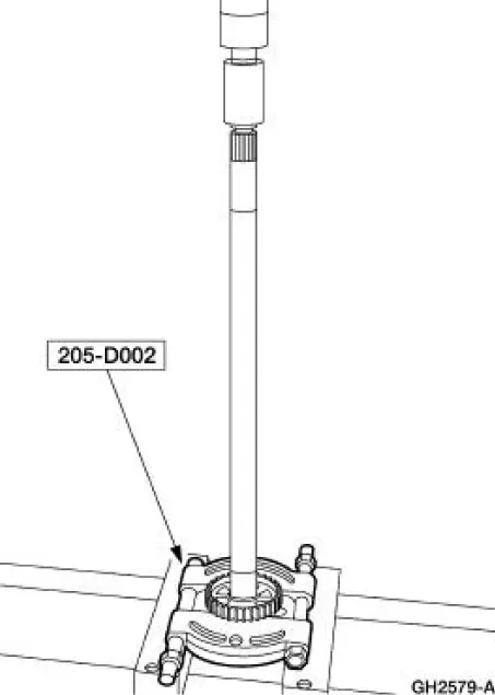
Pinion Bearing Cone Remover 205-D002 (D79P-4621A) |
 |
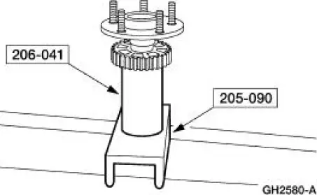
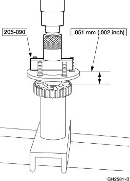
Axle Bearing/Seal Plate 205-090 (T75L-1165-B) |
 |
Sensing Ring Replacer 206-041 (T89P-20202-A) |
Removal
1. Remove the rear axle shaft bearing.
2. Using the special tool, remove the anti-lock brake sensor indicator from the axle shaft.
Installation
1. Using the special tools, align the rear anti-lock brake sensor indicator to the rear axle shaft.
2. Using the special tools, press the rear anti-lock brake sensor on the rear axle shaft to specification.
3. Install the rear axle shaft bearing.
 Hydraulic Control Unit
Removal
1. Disconnect the battery ground cable(14301).
2. Disconnect the anti-lock-brake control module electrical connector.
3. NOTE: The 4 wheel anti-lock brake system (4WABS) with traction
cont ...
Other materials:
Pinpoint Test G: LFC 16/DTC B1925 - Passenger Air Bag Circuit Shorted to
Battery or Ignition
Normal Operation
The restraints control module (RCM) checks for passenger air bag circuit
shorts to battery or ignition
by monitoring the voltage of circuits 607 (LB/OG) and 616 (PK/BK) at pins 6
and 7. If the RCM detects
a short to battery or ignition ...
Connecting Rod - Bushing Diameter
1. Measure the inner diameter of the connecting rod bushing, if equipped.
Verify the diameter is
within specification.
Refer to the appropriate section in Group for the procedure.
If out of specification, install new components as necessary. Refer
...
Supply Manifold
Removal
WARNING: Do not smoke or carry lighted tobacco or open flame of any
type when
working on or near any fuel related components. Highly flammable mixtures are
always present
and can ignite. Failure to follow these instructions can result in personal
in ...
